Digital + Analog Labs
Digital Input and Output
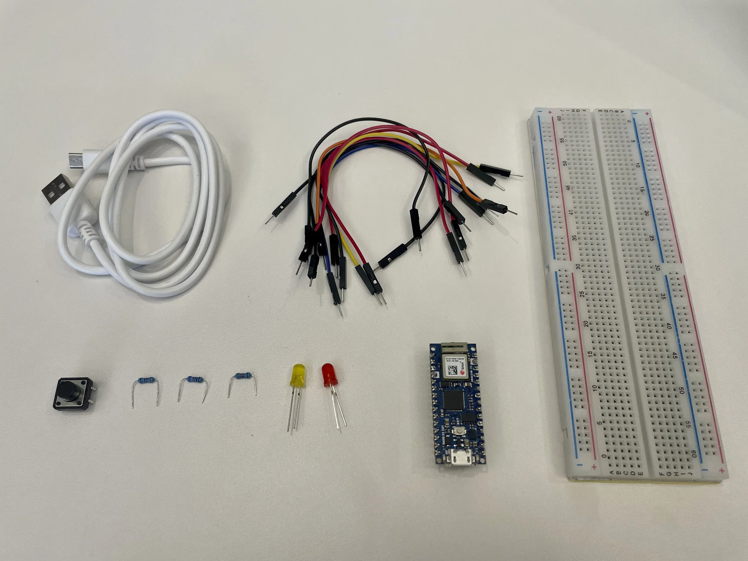
1 Arduino Nano 33 IoT
Jumper wires
1 solderless breadboard
2 LEDs
1 10-kilohm resistor
1 pushbutton
2 330-ohm resistors instead of 220-ohms
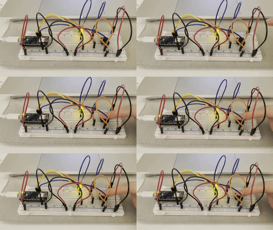
Prepare the breadboard + Add a digital input (a pushbutton) and digital outputs (LEDs)
Program the Arduino
The 1st attempt — "avrdude: butterfly_recv(): programmer is not responding" This was fixed by pushing the reset button quickly after I clicked on the upload button.
The 2nd attempt — Done uploading but nothing happened. The indicator light in the upper left corner of Arduino is flashing. I did the Blink test, which ended up with the light on but no blink.
The 3rd attempt — Done uploading but nothing happened. The indicator light in the upper left corner of Arduino doesn't work, which means (I guess) the code didn't go into the Arduino.
The 4th attempt — After meeting with Enrique, it is good to know that Arduino and breadboard are supposed to fit tightly, but the connection between my Arduino and breadboard is loose. After pressing the Arduino very hard, the lab was successful. The last failure might be caused by the quality of the breadboard I bought.
Unexpectedly, I spent eight hours in total on this "Hello World" of Arduino. It was a bit overwhelmed to build the circuits as a beginner when it comes to troubleshooting. It took me the first two hours to find out that the breadboard was not as fragile as I thought, and finally I learned to build a basic circuit on a breadboard in a relatively short time. Also, keep in mind to purchase a good-quality breadboard. Thanks to everyone who helped me along with the process.
Analog Input
1 Arduino Nano 33 IoT
Jumper wires
1 solderless breadboard
2 LEDs
2 10-kilohm resistors
1 potentiometer
2 force sensing resistors
2 200-ohm resistors instead of 220-ohms
1 photocell instead of 1 phototransistor; the phototransistor has an anode and a cathode while the photocell does not have polarity
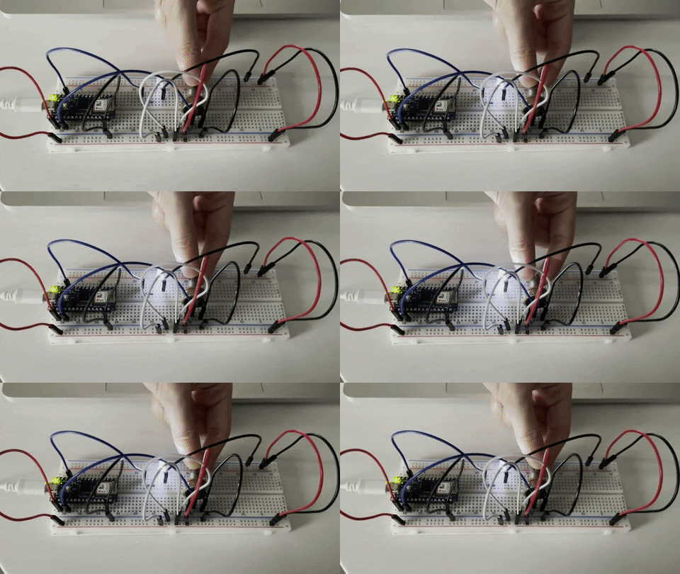
Add a potentiometer and LED + Program the module
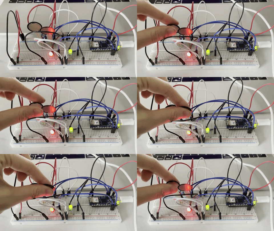
Finding the sensor range + Use the FSR to control the LEDs
Analog Output with Tone
1 Arduino Nano 33 IoT
Jumper wires
1 solderless breadboard
1 100-ohm resistor
1 8-ohm speaker
1 10-kilohm resistor
1 force sensing resistor
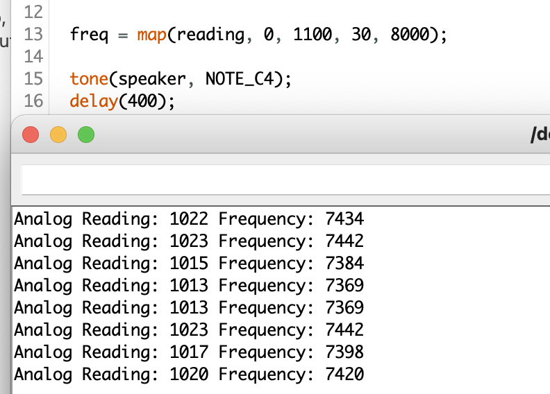
Prepare the breadboard + Connect the sensors and the speaker + Check the sensor input range + Play tones
Analog Output with ServoMotors
1 Arduino Nano 33 IoT
Jumper wires
1 solderless breadboard
1 potentiometer
1 force sensing resistor
1 10-kilohm resistor
1 RC servomotor
